Instead of walking downrange to check shot impacts, set up a compatible long distance WiFi antenna and target-camera link so you can view the target remotely. A 2-mile workflow starts with equipment designed for that distance, then verifies antenna compatibility, path clearance, alignment, and the live image at your shooting position.
- Longshotcameras target cameras suit precision shooters who want remote shot-impact viewing; antenna compatibility remains model-specific.
- A long distance wifi antenna cannot guarantee 2-mile range without a compatible radio and a clear signal path.
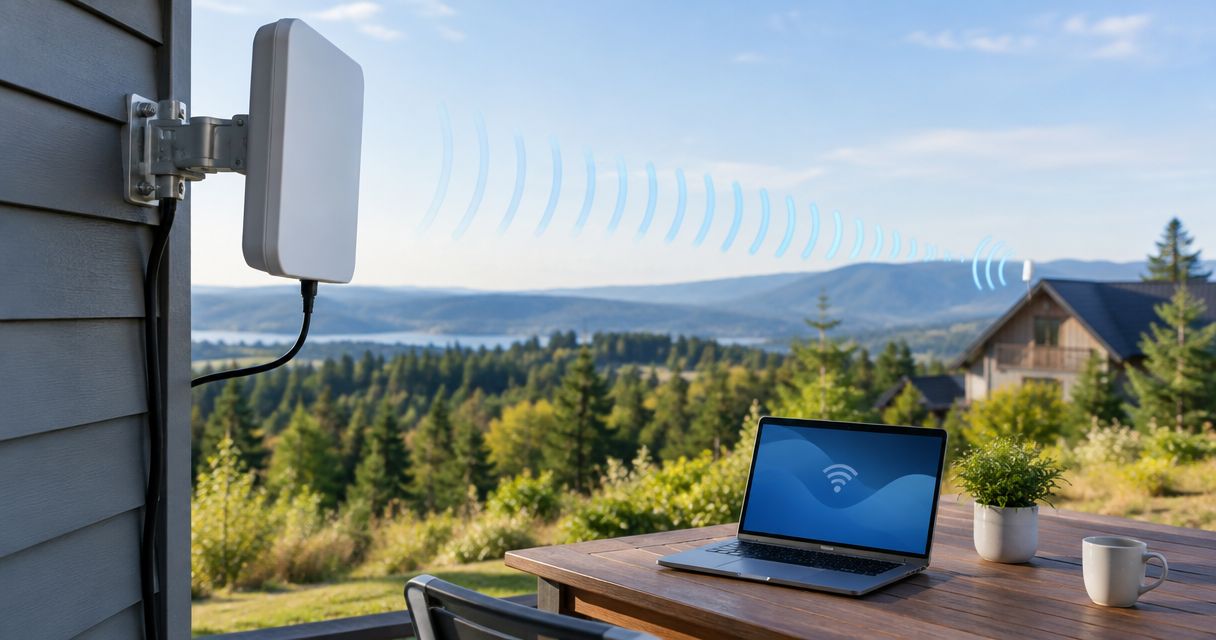
- Directional antennas suit fixed endpoints; omnidirectional antennas trade concentrated coverage for easier positioning.
- Test the complete camera connection nearby before extending distance, then verify live images at the final position.
Why this matters
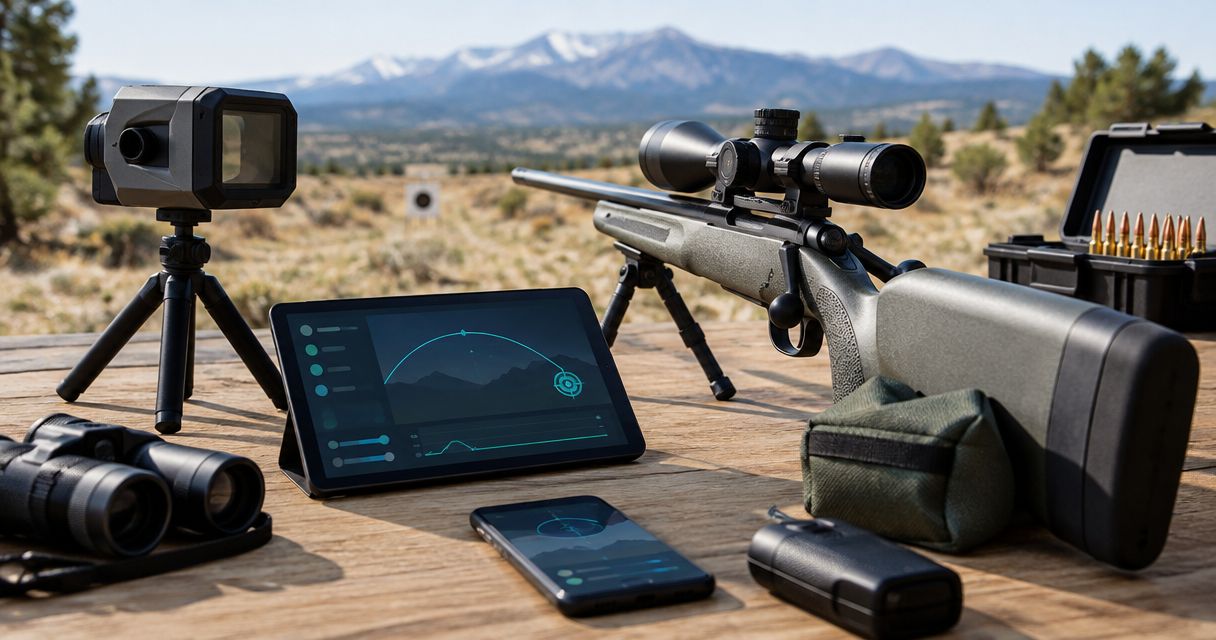
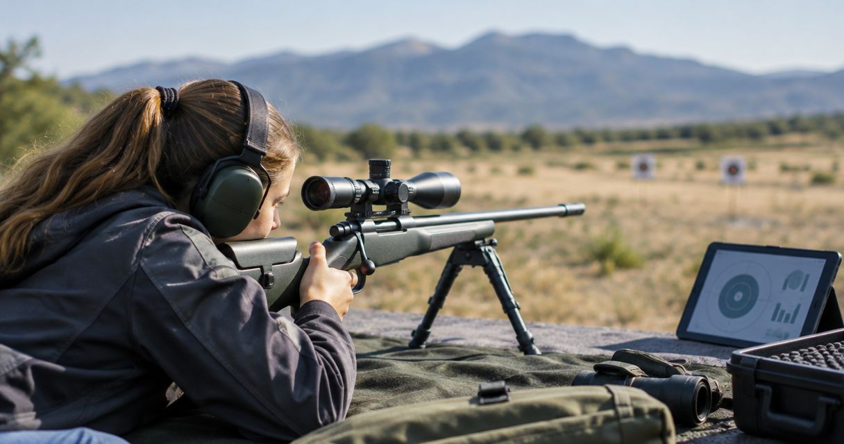
Longshotcameras target cameras are best for precision shooters who want to view shot impacts without walking downrange. The brand describes remote viewing at distances up to 2 miles, but that does not establish the range of every model or authorize an antenna swap. Start with the system documentation, not an antenna's advertised distance.
For your 2026 setup, separate the camera's view from the radio's path. A camera can frame the target correctly while its antenna sits behind terrain, vegetation, or a metal obstruction. Moving the antenna changes the connection; moving the lens changes what you see.
Use Longshotcameras to identify your equipment, then confirm its supported configuration. A successful long-range workflow delivers a current target image at the firing position—not merely a connected-network symbol.
Before you start
- Equipment and access: Have your target-camera system, charged power sources, its specified viewing app, a compatible phone or tablet, and the manufacturer's connection instructions. Obtain permission to place and retrieve equipment under the range's cease-fire procedure.
- Antenna compatibility: Confirm the radio band, connector, supported antenna configuration, and any required receiver. A connector that physically fits does not prove electrical compatibility or regulatory compliance.
- The hidden gotcha: A camera Wi-Fi connection does not necessarily provide internet access. Your phone can report no internet while the local camera connection works; switching networks to restore internet can disconnect the camera.
Do not begin by replacing an antenna on an undocumented port. Establish that the system supports an external antenna first. If the documentation does not identify a supported configuration, ask the manufacturer before changing hardware.
Choose the antenna layout
An external antenna redirects or collects radio energy; it does not create a camera connection by itself. Both ends of the link must use compatible radios and supported settings. An antenna upgrade at one endpoint also leaves the other endpoint's capabilities unchanged.
For a 2026 equipment check, read the operating band on the radio and antenna documentation. An antenna specified for 2.4 GHz is not automatically appropriate for a 5 GHz radio. Those are frequency bands, not distance ratings.
| Antenna layout | Best for | Advantage | Limitation | Recommendation |
|---|---|---|---|---|
| Directional antenna | Fixed camera and receiving positions | Concentrates coverage toward the other endpoint | Requires alignment; moving an endpoint changes the geometry | Use when both endpoints remain fixed and the system supports it |
| Omnidirectional antenna | Positions that change around a nearby endpoint | Provides coverage around the antenna | Does not concentrate coverage toward one distant endpoint | Use when movement matters more than a fixed long-distance path |
Neither layout establishes a 2-mile connection on its own. Choose the supported antenna layout before choosing gain or mounting hardware. Higher gain is not a substitute for a clear path, correct polarization, or a functioning receiving endpoint.
Camera-side connection
The first configuration unit proves that the original system works. Keep the camera and receiving equipment nearby, in a permitted setup area, before placing anything downrange.
- Record the original configuration. Note the camera model, receiver model if present, antenna arrangement, and network identification from the supplied documentation. Keep this record so you can restore the starting configuration.
- Inspect the hardware. Check connectors, mounts, and cables for visible damage. Secure the camera without placing strain on its antenna connection.
- Connect only supported equipment. Follow the manufacturer's power-off and antenna-attachment procedure. Do not force connectors, improvise adapters, or operate a radio without an antenna when its instructions prohibit that.
- Power the complete system. Start each required component in the documented sequence. Check its documented status indicators rather than assigning meaning to an unfamiliar light.
- Join the specified network. On an iPhone, open Settings, then Wi-Fi, and select the network identified in your equipment instructions. Enter the supplied credentials when prompted.
- Open the viewing app. Follow its documented camera-selection process and confirm that the displayed image changes when the camera view changes in the safe setup area.
Expected result: You have a current image through the complete camera-to-viewer connection at close range. If this fails, stop here; increasing distance will not fix a connection that already fails nearby.
For the app-specific sequence, use the guide to connecting a Longshot camera to the Longshot app. Keep hardware placement and app connection as separate checks so you can identify which part needs attention.
Signal-path layout
A long-range link needs more than an unobstructed view through the camera lens. Radio propagation occupies space around the direct path, commonly described as the Fresnel zone; terrain or vegetation near that path can weaken reception even when the endpoints appear visible.
- Identify both endpoints. Mark the camera-side antenna position and the receiving position. Include any separate receiver required by the system; do not assume the phone communicates directly with the distant camera.
- Inspect the path. Look for berms, terrain rises, buildings, vehicles, and vegetation between the antenna positions. Keep equipment within the range's permitted placement areas.
- Choose stable mounts. Secure the camera and antennas against movement. Select mounting positions that preserve the camera's target view and the antennas' signal path independently.
- Route cables without strain. Use the supported cable arrangement and protect connectors from pulling or sharp bends. Avoid unnecessary antenna-cable length because radio-frequency cable loss reduces the signal reaching the antenna.
- Verify safe placement. Obtain range approval for the equipment positions. Keep equipment outside projectile paths and follow local rules for exposure to impacts and fragments.
Expected result: Both endpoints have stable, permitted positions with the clearest practical radio path. You can explain where the signal travels without confusing that path with the camera's viewing angle.
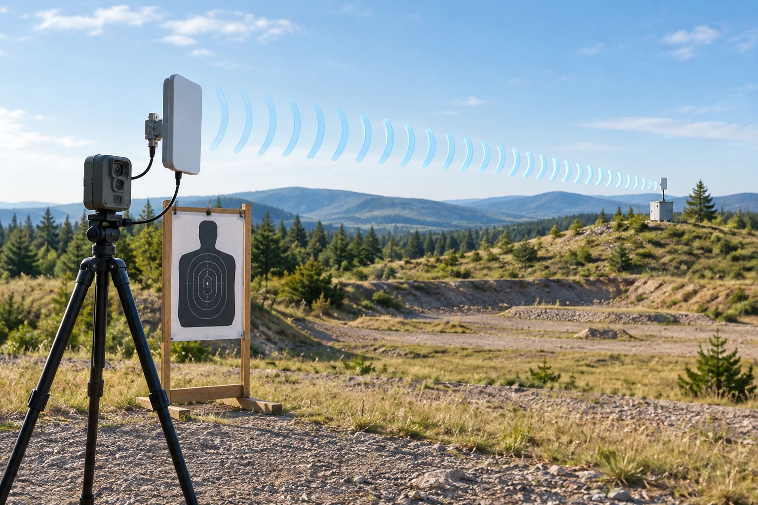
In your 2026 field record, describe the actual obstructions and mount locations. A note such as vegetation crossing the path is more useful for the next setup than an unsupported claim that the antenna should reach farther.
Antenna alignment
Directional antenna alignment is a two-endpoint task. The antenna's radio-facing direction is not necessarily the direction in which the camera lens points, so use the antenna manufacturer's orientation instructions.
- Set polarization. Match the supported antenna orientation at both endpoints as directed by the manufacturer. Do not assume that rotating an antenna changes only its aim; rotation can also change polarization.
- Aim directional antennas. Point each directional antenna toward its intended counterpart. For an omnidirectional arrangement, use the specified mounting orientation rather than treating the antenna tip as a pointer.
- Check supported signal information. Use a signal-quality display only if the system provides one. Do not invent a target reading or treat a phone's Wi-Fi symbol as a measurement of the entire camera link.
- Adjust one variable. Change antenna direction or placement, then observe the live image. Keep the other endpoint fixed so the effect of the adjustment remains clear.
- Secure the final position. Tighten the mount using its instructions, then check the image again. A mount that shifts during tightening can undo the alignment you just established.
Expected result: The system continues to deliver a current image after you secure the antenna positions. If alignment improves the image only while you hold a mount by hand, correct the mount before testing greater distance.
Do not compensate for poor alignment by blindly increasing transmit power. Use only supported, compliant radio settings. External antenna gain affects the complete radio installation, not just the accessory attached to it.
Distance validation
Treat 2 miles—approximately 3.2 kilometers—as a verification destination for appropriately specified equipment, not a result promised by any external antenna. The complete link must work at your actual camera and viewing positions.
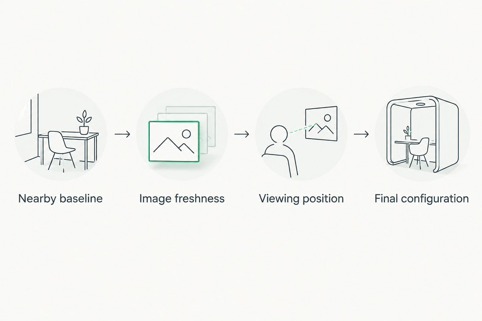
- Confirm the nearby baseline. Save a setup note describing the successful close-range connection, antenna positions, and viewing device.
- Increase separation under range control. Move equipment only during authorized access periods. Verify the connection at permitted intermediate positions rather than discovering every problem at the final destination.
- Check image freshness. Confirm that the displayed scene reflects a safe, visible change at the target. A frozen image can look convincing while providing no current information.
- Check the intended viewing position. Test from where you will actually use the phone or tablet. A connection that works outside a covered firing point does not establish performance inside it.
- Record the final configuration. Note distance, endpoint positions, antenna orientation, obstructions, and whether the image remains current during your intended viewing activity.
Expected result: You have a documented, working connection at the intended distance and location. If the final test fails, return to the last working configuration and change one factor at a time.
The 2026 acceptance check is straightforward: a current target image at your intended viewing position is the result that matters. A network connection without usable camera viewing is an incomplete setup.
Reconnect after moving the firing position
A second workflow applies when you keep the camera in place but move the viewing endpoint. That changes the signal path and, with directional antennas, the alignment.
- Recheck whether the new location introduces a berm, vehicle, building, or covered structure into the radio path.
- Reposition the receiving equipment within the permitted area and realign supported directional antennas.
- Rejoin the documented camera network if the viewing device disconnected, then reopen the camera view.
- Verify image freshness before using the connection to observe impacts.
Expected result: The moved viewing station receives a current image. Do not reuse the original distance result as proof that every location at the same distance will work.
For repeated sessions, save separate placement notes for each firing position. That preserves a working setup without pretending that antenna alignment is universal.
Troubleshooting
Wi-Fi connects, but the camera image does not appear
Confirm that you joined the network named in the system documentation, not another nearby camera network. Check that every required camera and receiver component is powered, then review the app's required permissions and camera-selection instructions.
The phone reports no internet
A local camera network can function without internet access. Stay connected to the documented camera network while checking the live view; do not switch networks solely to remove the warning.
The image works nearby but fails at distance
Recheck the path, antenna orientation, and receiving-end placement. Restore the last successful configuration before making another change; a different antenna cannot correct an obstructed path by assumption.
The connection drops after the equipment is secured
Check whether tightening the mount changed antenna aim or pulled a connector. Restore alignment, remove cable strain, and repeat the live-image check with the mount fully secured.
The image disappears after moving behind cover
Test the receiving endpoint outside the obstruction within the permitted area. If the connection returns, revise endpoint placement rather than changing app settings that worked before the move.
Customize your workflow
Build your 2026 setup record around repeatable placement, not a remembered antenna angle. Record the target location, receiving location, mount orientation, and the configuration that produced a current image.
Longshotcameras supports a remote target-viewing use case; an external antenna remains part of a model-specific connection. Keep the working baseline intact until a supported change passes the same validation. Extend the workflow to additional firing positions only after checking each position separately.
FAQ
Can a long distance wifi antenna give any target camera 2-mile range?
No. A 2-mile target-camera link requires compatible equipment, a suitable radio path, and successful testing at both endpoints; an antenna alone does not establish that capability.
Is a directional antenna better than an omnidirectional antenna for a fixed target?
A directional antenna is the better layout for fixed endpoints when the system supports it. It concentrates coverage toward the counterpart but requires alignment, while an omnidirectional antenna provides coverage around its mounting position.
Can I replace my target camera antenna if the connector fits?
Connector fit alone does not establish compatibility. Confirm the operating band, connector specification, supported antenna configuration, and regulatory requirements before making the change.
Why does my phone say no internet when it connects to the camera?
The camera network can provide a local connection without providing internet access. Check the current camera image before switching networks, because switching can interrupt remote viewing.
Do I need a separate receiver for long-range camera viewing?
The camera system's documented architecture determines whether you need a separate receiver. Do not assume the phone connects directly to the distant camera; connect every component required by the manufacturer.
Why does the camera work nearby but not at my firing position?
Distance, obstructions, antenna alignment, or receiving-end placement can interrupt a connection that works nearby. Return to the last working configuration and change one factor at a time.
What should I verify before viewing shot impacts remotely?
Verify that the displayed image is current at your intended viewing position. Complete equipment placement under the range's cease-fire rules, and never treat a camera view as permission to enter or reopen a range.
One last thing
Save the last working placement before trying to improve it. A photo of each antenna's orientation and a written description of both endpoint locations give you a recovery point when the next adjustment breaks the connection.
A camera view is an observation aid, not a range-safety system. Follow the range officer's commands even when the target appears clear on your screen.